We welcome any request for the environmental technological process. We promise timely delivery of the best possible solution.


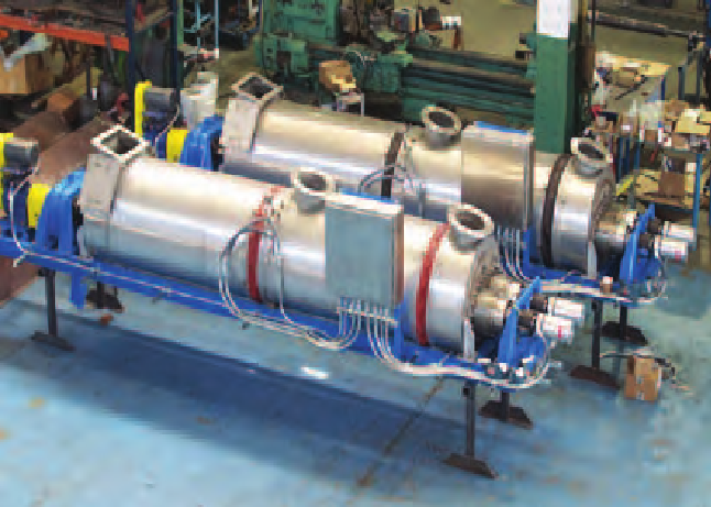
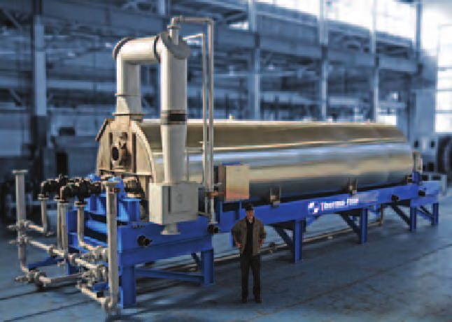
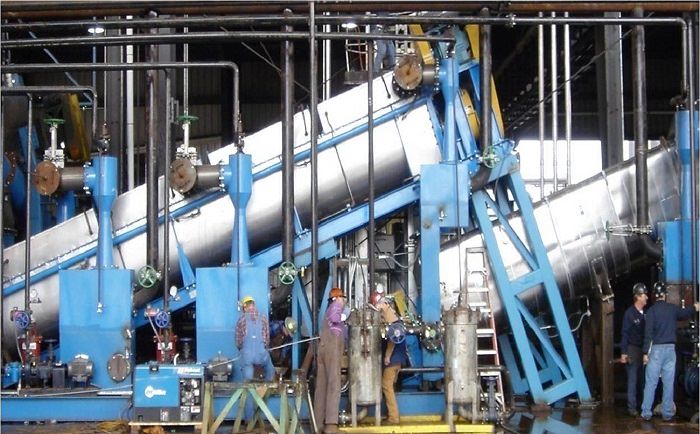
Therma-Flite screw processors: high efficiency, low profile
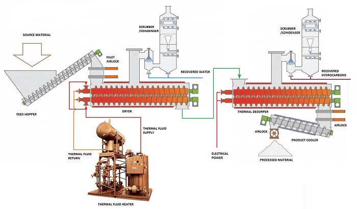
Thermal desorption system is a turn-key solution, and includes all the necessary components to:
- Hold and meter feed stock into the desorption chamber
- Provide an airlock to the inlet and discharge of the unit
- Cool the material exiting the desorption chamber
- Condense volatiles for collection.
Tank bottom sludge and soil remediation
Condense and recover hydrocarbons in one easy step!
Proposed TDU system heat residual material to 1,000+ degrees Fahrenheit, so that hydrocarbons and water are evaporated and then condensed and recovered.
These tank bottoms may be discarded after they have been thermally treated. Multi-stage systems make the process even simpler by removing water in one unit, while removing hydrocarbons in a second.
Drill cuttings dryers
Process 1.5 - 500 tons per day with 99.5% hydrocarbon recovery!
Thermal desorption systems volatilize and recover 99.5% of hydrocarbons from drilling mud. Oil, diesel and other synthetics are often used as lubricants in drilling for natural gas. After this mud is recovered and centrifuged, the slurry typically contains high levels of water, diesel, and even crude oil.
TDU processes can accept feed stock with hydrocarbon percentages greater than 70%, effectively collecting and condensing water, diesel and other hydrocarbon vapors. In applications such as natural gas drilling where diesel and water constitute the liquid phase, diesel is typically filtered, then resold or reused as a lubricant for future drilling.
TDU units in operation in the U.S. process drill cuttings from shale drilling - this feed stock is generally 10% to 30% diesel, and 20% water. Recovery rates for diesel typically range from 97% to 99.5%.
Hazardous waste processing
Delisting Resource Conservation and Recovery Act (RCRA) waste!
Proposed TDU are excellent for delisting RCRA waste. Drums, cans, glass and plastic containers are just some of the items that carry hydrocarbon-laden materials such as paint, perfume, degreaser, oil, resins, and hair spray.
The heart of the systems, the desorption unit, includes intermeshed rotors. In this chamber, feed stock is heated indirectly under a slight negative pressure in a sealed, anaerobic environment. Thermal fluid is circulated throughout the rotors and outer jacket of the desorption chamber. The proprietary dual rotor design is self-clearing and feed stock which might otherwise bake on to the rotors is easily removed. Different mixing programs may be set in the Programmable Logic Controller (PLC) which will increase the heat transfer into the feed stock.
Ingenious Technology
The heart of the systems, the desorption unit, includes intermeshed rotors. In this chamber, feed stock is heated indirectly under a slight negative pressure in a sealed, anaerobic environment. Thermal fluid is circulated throughout the rotors and outer jacket of the desorption chamber. The proprietary dual rotor design is self-clearing and feed stock which might otherwise bake on to the rotors is easily removed. Different mixing programs may be set in the Programmable Logic Controller (PLC) which will increase the heat transfer into the feed stock.
A variety of heat transfer fluids may be used to heat product up to 850-degrees Fahrenheit. A second stage system can be incorporate to heat the product to above 1200-degrees Fahrenheit. Most feed stocks may be de-volatilized to less than 0.05% remaining hydrocarbons. As the heated solids exit the desorption chamber, they pass through a second airlock and into a cooling screw conveyor. In the cooling screw, solids are indirectly cooled by circulating water through the jacketed wall of the screw. The temperature is further reduced by direct-contact quench cooling via atomizing sprays along the top of the cooling screw housing. The vapors exit the unit into a Venturi-effect, multi-stage condenser. Cooled and filtered condensate is used as the condensing fluid. The Venturi-effect condenser is highly-efficient with less than 0.01% hydrocarbons remaining in the non-condensable stream. The non-condensable stream is released through a duct to the air intake on the diesel generator providing the unit’s electrical power.
- Maximum product temperature: 1200-degrees Fahrenheit
- Maximum operating pressure: 350 psi
- Maximum operating vacuum: 50 millitorr.