

We welcome any request for the environmental technological process. We promise timely delivery of the best possible solution


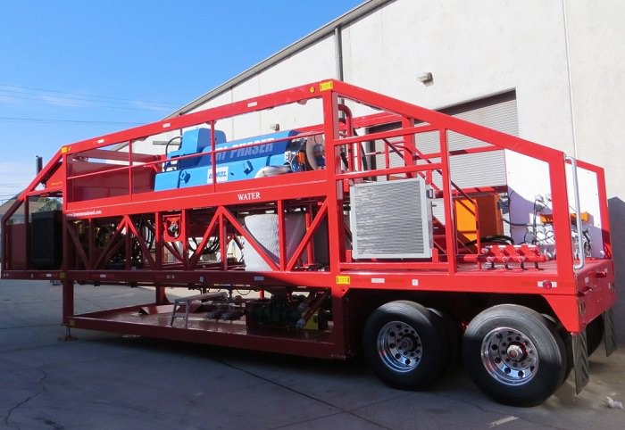
Tri-Phaser Unit
The Tri-Phaser unit is a self-contained mobile processing system for the secondary phase of separation of liquefied industrial sludge. In addition, it can provide a power source to drive various peripheral equipment to extract and pre-process sludge.
The feed enters the rotating bowl through a stationary feed pipe and is accelerated out of the feed chamber towards the bowl wall. The centrifugal force generated by the rotation rapidly settles the solid particles against the bowl wall. They are transported by the helical screw conveyor towards the conical end of the bowl and ejected through the solid discharge ports.
As the clarified liquid flows along the bowl, centrifugal forces cause the oil and water to separate. This can only be achieved when the correct pretreatment with heat and/or additives has been completed.
The water phase moves towards the periphery of the wall and the oil is displaced towards the axis of the bowl. Both oil and water travel axially toward the opposite end from which solids are discharged. A separation disc at the large end of the screw conveyor prevents the remixing of the two liquid phases prior to their discharge. Purified water that passes under the separation disc is discharged over adjustable weir plates on the head wall of the decanter bowl into a separate housing. Purified oil exits via dip tubes fitted through the bowl wall into a separate housing.
Equipment Specifications
Trailer Specifications |
|
|
Length |
480" (12.2 m) |
|
Width |
96" (2.44 m) |
|
Height |
156" (3.96 m) |
|
Weight |
Nominal 55,000 lbs (24.9 ton) |
|
Brakes |
S cam, air operate spring brakes |
|
Wheels and Tires |
11R-225 Tires mounted on aluminum wheels. |
Equipment Specifications |
|
|
Fuel Capacity |
Nominal 600-gallon reservoir with level gauge |
|
Engine |
Caterpillar C-9 275 BHP @ 2200 RPM |
|
Three Phase Centrifuge |
Three phase centrifuge with full hydraulic main and back drive. Speed 2,800 - 3,300 RPM. Maximum Gravity 3,165 G's. Maximum Capacity 18-20 tons per hour |
|
Light Phase Pump |
Progressive Cavity Pump. 144 GPM @ 87 PSI |
|
Heavy Phase Pump |
Progressive Cavity Pump. 144 GPM @ 87 PSI |
|
Water and Oil Collection Tanks |
Two tanks for collection of water and oil after three phase centrifuge |
|
Solid Conveyor |
Discharge solids from three phase centrifuge |
|
Hydraulic System |
System 1 - 52 GPM closed loop system powers the centrifuges main drive at pressures up to 4,000 PSI. System 2 - 23 GPM open loop system powers the centrifuge back drive at pressures up to 3,700 PSI. System 3 - 120 GPM main open loop system that is flow and pressure compensated up to 2,500 PSI powers the balance of the machine and provides for 3 auxiliary circuits to power peripheral equipment |
|
Unit Control System |
The unit equipment listed is operated from a central control station |
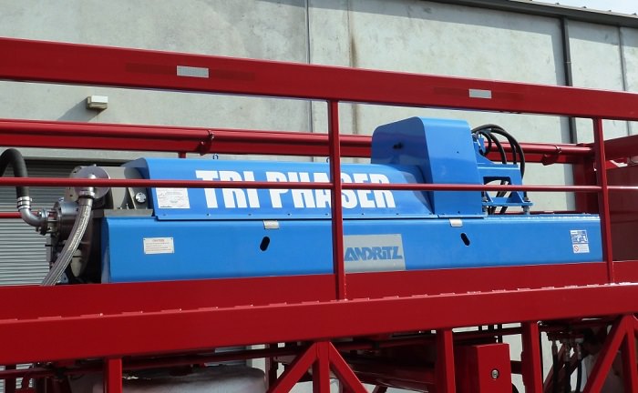
Three Phase Centrifuge
The heart of the system is a horizontal three phase decanter centrifuge that has been modified to provide removal of multiple phases on a continuous basis. The centrifuge features a fully adjustable hydraulic main drive and a unique self-regulating hydraulic back drive. This allows the elimination of traditional methods using a two stage separation system such as two phase decanter centrifuge to remove the solids, followed by a disc separator to split the two liquid phases and complete separation in one stage using one unit.
The combination of these two drives provides a system with multiple advantages over a standard fixed speed main drive and geared back drive, which include the following:
- No gear box to maintain
- No shear pins to replace
- No components breakage due to excessive overloading
- No torsional vibration (chatter). Vibration is hydraulically dampened
- Direct reading of torque in discharge
- Minimum moisture in discharge
- Cleaner centrate
- Less sensitive to feed fluctuations
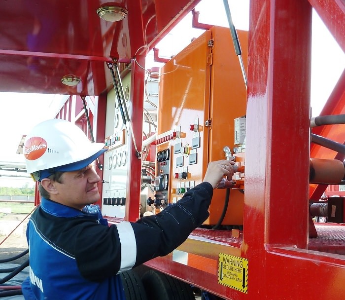
Unit Control System
All hydraulically driven equipment is operated from a central control station. The control station is equipped with controls to adjust the speed and, where applicable, the rotation of the centrifuge as well as pumps and conveyor. It also has instruments for monitoring each of the hydraulically driven components' loads and, where applicable, rotating speeds. Additional controls for diesel engine are also at this location. The entire unit as well as the peripheral equipment is powered by the onboard hydraulic system which utilizes an advanced load-sensing technology to reduce wear and tear and improve fuel economy.
Water and Oil Collection Tanks
1 - Water collection tank
2 - Oil collection tank
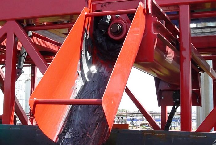
Solid Conveyor
Solid Conveyor to discharge solids from three phase centrifuge.
Solids is evacuated by hydraulic screw adjustable conveyor.
Conveyor has secure mode for transportation.
Engine Specifications
|
Cylinders and Arrangement |
In-line six cylinder |
|
Bore |
112.0 mm (4.41 inch) |
|
Stroke |
149.0 mm (5.87 inch) |
|
Aspiration |
Air-to-air aftercooled |
|
Displacement |
8.8 L (537 in3) |
|
Firing Order |
1-5-3-6-2-4 |
|
Rotation (flywheel) |
Counterclockwise |
|
Valve Lash (inlet) |
0.38 mm (0.015 inch) |
|
Valve Lash (exhaust) |
0.64 mm (0.025 inch) |
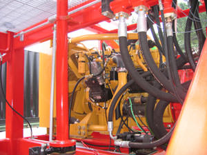
Hydraulic Systems
System 1 - 52 GPM closed loop system powers the centrifuges main drive at pressures up to 4,000 PSI.
System 2 - 23 GPM open loop system powers the centrifuge back drive at pressures up to 3,700 PSI.
System 3 - 120 GPM main open loop system that is flow and pressure compensated up to 2,500 PSI powers the balance of the machine and provides for 3 auxiliary circuits to power peripheral equipment.
All systems are equipped with full flow filtration while the main open loop system provides full flow cooling. The 270 Gallons nominal capacity hydraulic reservoir is equipped with temperature and level gauges while the hydraulic filters and minimum tank level are monitored electrically.
Light and Heavy Phase Pump
1 - Light (oil) Phase Pump
2 - Heavy (water) Phase Pump
